Needle penetration
What is this: the steel-needle trigger method for thermal runaway, per Appendix C clause C.5.3.3. A needle is driven into the trigger cell to create an internal short between the electrodes.
Specification
"C.5.3.3 Needle penetration method to trigger thermal runaway: a) Needle material: Steel; b) Needle diameter: 3 mm – 8 mm; c) Needle tip shape: Conical, with an angle between 20° – 60°; d) Needle penetration speed: 0.1 mm/s – 10 mm/s; e) Needle penetration position and direction: Choose the position and direction that can trigger thermal runaway in the battery cell (for example, perpendicular to the electrode direction); f) Needle penetration stop condition: Continue until thermal runaway occurs, or until the needle penetration depth reaches 90 % of the battery cell's dimension in the direction of the needle penetration. g) The needle penetration hole in the battery pack should be sealed with sealing material to suppress the venting from the needle penetration hole."
| Parameter | Value |
|---|---|
| Material | Steel |
| Diameter | Ø 3 mm – 8 mm |
| Tip shape | Conical, 20° – 60° included angle |
| Penetration speed | 0.1 mm/s – 10 mm/s |
| Direction | Perpendicular to electrode direction (recommended) |
| Stop condition | TR confirmed, or depth ≥ 90 % of cell dimension along needle axis |
| Hole in pack | Sealed to suppress venting through the hole |
Why these parameters
- Steel needle — chemically inert at the temperatures involved, mechanically robust enough not to deform during penetration.
- Ø 3–8 mm — large enough to reliably bridge multiple electrode layers but small enough not to mechanically destroy the cell before the short can develop.
- Conical tip 20°–60° — sharp enough to penetrate without crushing, blunt enough not to deflect along electrode layers.
- Speed 0.1–10 mm/s — slow enough that the operator can stop precisely on TR confirmation; fast enough that the test does not run for hours.
- Perpendicular to electrode direction — maximises the number of cathode/anode layer pairs the needle bridges, increasing short-circuit current and the chance of triggering TR.
The 90 % depth limit
The needle stops at 90 % of the cell dimension to avoid puncturing the opposite face of the cell housing. If TR has not occurred by 90 % depth, the test moves to the no-trigger fallback — the manufacturer must demonstrate none of the three recommended methods would have triggered.
Sealing the pack hole (C.5.3.3 g)
The needle has to pass through the pack housing to reach the trigger cell. The hole this creates is a vent path that does not exist in service, and would unfairly help the pack pass the smoke/no-fire criteria. So the standard requires the hole to be sealed with sealing material to suppress venting through it.
This is a non-trivial procedural requirement — the seal has to hold during the pressure transient of TR. Typical practice is a high-temperature silicone or epoxy plug, applied around the needle shank just before TR is anticipated.
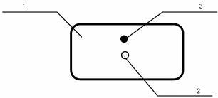 Figure C.2 from GB 38031-2025 (PDF p. 37). 1 — triggering object; 2 — needle penetration position; 3 — temperature sensor.
Sensor placement
"When triggering with needle penetration, the temperature sensor should be placed near the short-circuit point, or the temperature of the needle can also be used (as shown in Figure C.2)." (C.5.3.6 b)
See monitoring and sensors. Two valid placements:
- Near the short-circuit point — sensor on the cell surface adjacent to the needle entry.
- On the needle itself — using the steel needle as a temperature probe (well-coupled to the short-circuit zone).
Tradeoffs
Pros: - Fastest to TR — TR typically follows the short within seconds for a high-SOC cell. - Closest to a real internal-short failure mode (mechanical insult through the separator). - Trigger device is simple (a needle and a linear actuator).
Cons: - Pack housing must be penetrated and the hole sealed — operationally awkward. - Penetration position relative to internal cell features (current collector tabs, jellyroll layers) affects whether TR triggers reliably. - Hard to apply repeatably to a cell that is already inside a pack with surrounding cells in the way.
Engineering note (non-normative): Needle position matters more than the standard hints. Penetrating through the cell tab area can short the tab to its neighbour rather than the internal layers, producing a short without TR. Penetrating through the centre of the active area perpendicular to the electrode stack is the most reliable trigger geometry.
Engineering note (non-normative): The seal on the pack hole (C.5.3.3 g) is sometimes underestimated. During TR the pack interior pressure can spike fast enough to blow a hastily-applied silicone plug. Use a fixture that mechanically clamps the seal in place, not just adhesive.
Cross-references
- Trigger methods overview
- External heating
- Internal heating plate
- Monitoring and sensors
- Runaway confirmation rule
Source: GB 38031-2025, Appendix C section C.5.3.3 (PDF p. 35–36); sensor placement in C.5.3.6 b) and Figure C.2 (PDF p. 37).