External fire
Verifies the battery pack or system survives engulfment in a gasoline fire without exploding. Fire is permitted during and after the test; only explosion is disqualifying.
| Clause (method) | 8.2.7.1 |
| Clause (pass criteria) | 5.2.7 a) |
| Object | pack / system |
| Status vs. 2020 | revised (both requirements and method) |
| Observation period | 2 h at test environment temperature, or until external temperature < 45 °C |
Pass criteria
"The battery pack or system, after undergoing the external fire test as per 8.2.7.1, should not explode."
The standard requires only no explosion. Fire (sustained burning, jet flames, ejected burning material) is not by itself a failure for this test, and the universal "no leakage / no housing crack / insulation ≥100 Ω/V" criterion does not apply here — the test object has just been engulfed in gasoline and burned for over two minutes.
Source: GB 38031-2025, clause 5.2.7 a) (PDF p. 12).
Pre-conditions
- Sample: Battery pack or system. The body structure that protects the pack/system may also be included in the fire test. (8.2.7.1.1)
- Pre-treatment: Standard, per clause 7.2.
- SOC: Highest working SOC per clause 6.1.10 (the standard does not override the default for the external fire test).
- Environment: Ambient temperature above 0 °C; wind speed ≤ 2.5 km/h. (8.2.7.1.2)
- Excluded chemistries: Nickel-hydride packs/systems are excluded from clause 5.2.7 (see 5.2.7 opening clause).
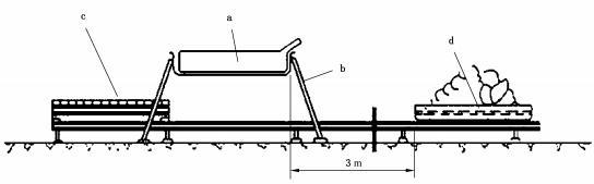 Figure 9 from GB 38031-2025 (PDF p. 23). a — test object; b — test stand; c — fireproof barrier (covered with fireproof bricks); d — flat tray containing gasoline. Gasoline pan and test object start ≥ 3 m apart for preheating.
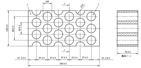 Figure 10 from GB 38031-2025 (PDF p. 24). Dimensions in mm. Fireproof barrier: SK 30; 30 %–33 % Al₂O₃; density 1 900–2 000 kg/m³; effective hole area 44.18 %; aperture rate 20 %–22 % volume ratio.
Test parameters
| Parameter | Value | Source |
|---|---|---|
| Test environment temperature | > 0 °C | 8.2.7.1.2 |
| Wind speed | ≤ 2.5 km/h | 8.2.7.1.2 |
| Pan footprint | Horizontal projection of pack +20 cm to +50 cm | 8.2.7.1.3 |
| Pan height above gasoline | ≤ 8 cm | 8.2.7.1.3 |
| Bottom layer of pan | Water | 8.2.7.1.3 |
| Gasoline surface to pack bottom | 50 cm, or vehicle ground clearance unloaded | 8.2.7.1.3 |
| Stage 1 — preheat | 60 s ignite ≥ 3 m from test object, then place pan beneath | 8.2.7.1.4 a) |
| Stage 2 — direct burn | 70 s direct flame exposure | 8.2.7.1.4 b) |
| Stage 3 — indirect burn | 60 s with fire-resistant brick screen over pan (or, by mutual agreement, another 60 s direct) | 8.2.7.1.4 c) |
| Stage 4 — remove | Move pan or test object away from fire | 8.2.7.1.4 d) |
| Fire-resistant brick — class | SK 30 | Fig. 10 (PDF p. 24) |
| Fire-resistant brick — Al₂O₃ | 30 % – 33 % | Fig. 10 |
| Fire-resistant brick — density | 1 900 – 2 000 kg/m³ | Fig. 10 |
| Brick screen — effective hole area | 44.18 % | Fig. 10 |
| Brick screen — aperture rate | 20 % – 22 % by volume | Fig. 10 |
Procedure
Steps from clause 8.2.7.1.4. Burn-time clocks start and stop only when the test object, fireproof barrier, and oil pan are all stationary (8.2.7.1.3).
- Confirm environment: ambient > 0 °C, wind ≤ 2.5 km/h. (8.2.7.1.2)
- Position the pack on the test stand. Place the gasoline pan beneath; the pan footprint exceeds the pack horizontal projection by 20 cm to 50 cm, the pan height is ≤ 8 cm above the gasoline surface, and a water layer is added at the bottom of the pan. (8.2.7.1.3)
- Set the gasoline-to-pack-bottom distance to 50 cm, or to the vehicle ground clearance (unloaded), whichever applies. (8.2.7.1.3)
- Stage 1 — Preheat (60 s): Ignite the gasoline at least 3 m away from the test object. After 60 s of preheating, move the oil pan under the test object (or move the test object and its support over the pan if the pan is too large to relocate). (8.2.7.1.4 a)
- Stage 2 — Direct burn (70 s): Expose the test object directly to the flames for 70 s. (8.2.7.1.4 b)
- Stage 3 — Indirect burn (60 s): Place the fire-resistant brick screen (SK 30, 30–33 % Al₂O₃, density 1 900–2 000 kg/m³, effective hole area 44.18 %) over the oil pan and continue for 60 s. By mutual agreement, this stage may instead be another 60 s of direct exposure. (8.2.7.1.4 c)
- Stage 4 — Remove: Move the oil pan or test object away from the fire source. (8.2.7.1.4 d)
- Observe at the test environment temperature for 2 h, or until the external temperature of the test object drops below 45 °C, whichever comes first. (8.2.7.1.4 d)
- After observation, evaluate against pass criterion 5.2.7 a) — the only failure mode is explosion.
After-test observation
Observe the test object for 2 h at the test environment temperature, or until the external temperature drops below 45 °C, whichever is first. (8.2.7.1.4 d)
The standard does not require post-test insulation measurement, leakage inspection, or housing-crack inspection for this test — the only criterion is no explosion.
What changed from GB 38031-2020
The 2025 revision tightens both 5.2.7 a) and 8.2.7.1:
- The four-stage burn sequence (preheat / direct / indirect / remove) and per-stage durations are now explicit in the standard.
- The fire-resistant brick screen specification is normative: SK 30, 30–33 % Al₂O₃, density 1 900–2 000 kg/m³, effective hole area 44.18 % (Figure 10).
- The bottom-of-pan water layer, pan-edge offset (+20 to +50 cm), and 8 cm pan-height limit are spelled out in 8.2.7.1.3.
Migration impact: New type approvals from 2026-07-01. Already-approved models from 2027-08-01. See Re-certification timeline.
Engineering notes (non-normative)
The notes below are practical interpretation, not part of the standard.
Engineering note (non-normative): The "stationary state" rule in 8.2.7.1.3 (burn clock starts/stops only when pan, screen, and pack are all motionless) matters operationally because the screen change between Stage 2 and Stage 3 is the most disruptive event in the test. If the screen is placed clumsily, a few seconds of unmeasured exposure can creep in. Plan the screen rig so it can be set down in one motion without disturbing the pan.
Engineering note (non-normative): The 50 cm gasoline-to-pack-bottom gap is a worst-case proxy for an underbody pool fire under a parked vehicle. If the vehicle's actual unloaded ground clearance is less than 50 cm the smaller value is used — this is the harder case. For high-clearance N-class vehicles the 50 cm value applies as the floor.
Engineering note (non-normative): Because the only failure criterion is explosion, instrumentation should focus on detecting deflagration / overpressure events (high-speed video, pressure transducers in the test cell), not on cell-level voltage or temperature. Cell-level degradation during the burn is expected and is not a failure mode here.
Related
- Pass/fail criteria: What "no fire, no explosion" means
- Glossary: Explosion, Fire
- Related tests:
- Thermal propagation (8.2.7.2) — the other thermal-stability test under 5.2.7
- Source: GB 38031-2025, clause 8.2.7.1 (PDF p. 23–24); pass criteria in clause 5.2.7 a) (PDF p. 12).