Internal heating plate
What is this: the inside-the-cell trigger method for thermal runaway, per Appendix C clause C.5.3.5. A small resistive plate is built into the cell at the centre of the coil or stack, then powered to drive TR from inside.
Specification — Table C.3
| Parameter | Value |
|---|---|
| Material | Cu + insulation layer, or other suitable resistive heating elements |
| Area | 15 mm × 15 mm to 60 mm × 60 mm |
| Thickness | ≤ 0.5 mm |
| Power (E < 500 Wh) | 150 W – 700 W |
| Power (E ≥ 500 Wh) | 200 W – 700 W |
| Placement | Centre of the coil or stack surface |
| Sealing of lead holes and wire ends | Resin glue (e.g. epoxy resin), or other suitable structural sealing methods |
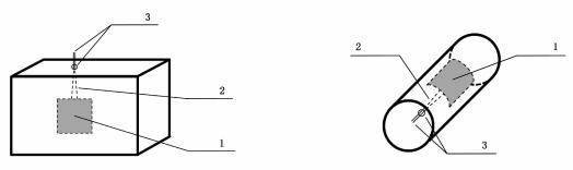 Figure C.1 from GB 38031-2025 (PDF p. 37). a) hard case and pouch cell; b) cylindrical cell. 1 — heating sheet; 2 — connecting wire; 3 — sealing position. The heating plate sits at the centre of the coil/stack surface; lead wires exit through a sealed hole in the cell housing.
How the cell is prepared
"C.5.3.5.1 The preparation process for the battery cell with an internal heating plate and its battery pack is as follows: a) Before preparing the battery cell with the internal heating plate, a suitable hole should be made in the outer casing of the battery cell to allow the connecting wires of the heating plate to be led out from inside the battery cell. b) Before packaging the battery cell, place the heating plate at the center of the coil or stack surface. c) After the battery cell is packaged, seal the lead-out hole on the outer casing of the battery cell and the ends of the heating plate's connecting wires (see Figure C.1). After sealing, proceed with the conventional manufacturing process to produce the battery cell. d) Assemble the battery cell into the battery pack using the conventional manufacturing process. Lead the connecting wires of the heating plate out from the battery pack, and seal the lead-out position."
This is the most invasive of the three trigger methods — the cell is rebuilt from the start with the heating plate inside. Figure C.1 in the standard shows the plate (1), connecting wires (2), and sealing position (3) for both hard-case/pouch cells and cylindrical cells.
Test procedure
"C.5.3.5.2 Test Procedure: Heat the triggering object. Stop triggering when thermal runaway occurs or when the temperature at the monitoring point defined in C.5.3.6 reaches 300 °C."
Same stop conditions as external heating:
- TR confirmed under the (a OR b) AND c rule, or
- Monitor T = 300 °C without TR — the no-trigger fallback.
Sensor placement
Same rule as external heating: sensor on the opposite side from the heating device. (C.5.3.6 c, Figure C.4)
For the internal heating plate, "opposite side" means: the plate sits inside the cell at the coil/stack centre, and the temperature sensor goes on the cell's outer face that lies directly opposite the plate's orientation. See monitoring and sensors.
Why this method exists
External heating works for many cells, but for thermally robust chemistries (LFP at high SOC, some NMC formulations with thermally-stable electrolytes) the heater can fail or the monitor can hit 300 °C without TR. The internal heating plate puts the energy inside the jellyroll, where:
- The cell's own internal thermal isolation works for the heater rather than against it.
- The energy density of the source is much higher than what an external surface heater can deliver per unit area.
- The trigger geometry mimics an internal hot spot from a manufacturing defect — which is the kind of fault the test is supposed to verify against.
For OEMs whose cells will not run away under the other two methods, this is typically the next attempt before claiming the no-trigger demonstration.
Power bands
The 150–700 W (or 200–700 W for ≥ 500 Wh cells) is much higher than typical internal cell currents would dissipate. The plate is small (≤ 60 × 60 mm) and thin (≤ 0.5 mm), so even at 700 W the time to TR is short — seconds to a minute.
Tradeoffs
Pros: - Most reliable trigger — energy is deposited inside the jellyroll, not at the cell exterior. - Mimics a realistic internal-defect failure mode. - Power and area are well-bounded by Table C.3.
Cons: - Cell must be purpose-built with the plate inside. A production cell cannot be retrofitted. - The lead-wire hole through the cell housing is a permanent modification that the OEM must declare in the C.3.5 d) list of modifications (see OEM documentation package). - Sealing must hold during cell formation, packaging, pack assembly, and the test itself. - Pack assembly must include lead routing for the plate wires out of the pack, which is another sealed lead-through (C.5.3.5.1 d).
Engineering note (non-normative): Cells built for this test are not the cells that go into customer vehicles. Treat the internal-heating-plate cells as test articles only — manufacturing them is fundamentally a custom process and they should not be installed in any vehicle that leaves the test site.
Engineering note (non-normative): The lead-through holes (one in the cell, one in the pack) are vent paths during TR. The standard requires sealing with epoxy or "other suitable structural sealing methods" but does not specify a pressure rating. Match the seal capability to the worst-case pack interior pressure during TR — typical NMC packs see hundreds of kPa transient.
Cross-references
- Trigger methods overview
- Needle penetration
- External heating
- Monitoring and sensors
- Runaway confirmation rule
Source: GB 38031-2025, Appendix C section C.5.3.5 and Table C.3, plus C.5.3.5.1 preparation steps and C.5.3.5.2 test procedure (PDF p. 36–37); sensor placement in C.5.3.6 c) and Figure C.4 (PDF p. 38).