Monitoring and sensors
What is this: where to place voltage and temperature sensors during the thermal propagation verification test, and how fast they must sample. Per Appendix C clause C.5.3.6 and Figures C.2–C.4.
Sampling
"Voltage or temperature monitoring should use the original circuit or an additional test circuit. The sampling interval for temperature data should be less than 1 second." (C.5.3.6 a)
The < 1 s sampling rate is the floor — finer is fine. Below 1 s is what the dT/dt ≥ 1 °C/s for > 3 s rule in runaway confirmation needs to actually resolve.
The standard does not separately specify a voltage sampling interval, but in practice voltage and temperature share the data acquisition system. Use the same < 1 s interval for both.
Sensor placement by trigger method
The placement rule depends on which trigger method is used. The reasoning in each case is to put the sensor where the cell's response — not the trigger device's response — is being measured.
Needle penetration (C.5.3.6 b, Figure C.2)
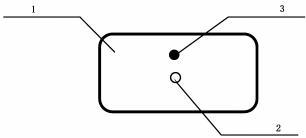 Figure C.2 from GB 38031-2025 (PDF p. 37). 1 — triggering object; 2 — needle penetration position; 3 — temperature sensor.
"When triggering with needle penetration, the temperature sensor should be placed near the short-circuit point, or the temperature of the needle can also be used (as shown in Figure C.2)."
The short-circuit happens at the needle tip. Place the temperature sensor:
- Near the short-circuit point — i.e. on the cell surface adjacent to where the needle enters or exits, or
- On the needle itself — using the needle as a temperature probe.
Figure C.2 shows the trigger object (1), the needle penetration position (2), and the temperature sensor (3) placed adjacent to the entry point on the cell.
See needle penetration for the trigger setup.
External heating (C.5.3.6 c, Figure C.3)
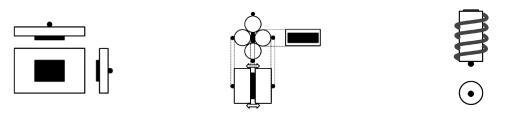 Figure C.3 from GB 38031-2025 (PDF p. 38). Sensor sits on the side opposite the heating device for each cell form factor.
"During heating triggering, the temperature sensor should be placed on the side opposite to the heat conduction, that is, installed on the side opposite the heating device."
For external heating, the heating device is on one face of the cell and the sensor is on the opposite face. This is so the sensor measures the cell's internal heating (from the runaway reactions) rather than direct conduction from the heater.
Figure C.3 shows three layouts:
- a) Hard case and pouch cell: heater on one large face, sensor on the opposite large face.
- b) Cylindrical cell — variant I: heater on side, sensor on opposite side.
- c) Cylindrical cell — variant II: heater on one end, sensor on opposite face.
The heater position must correspond to the sensor position (C.5.3.4) — i.e. they are on directly opposite faces, not arbitrary sides.
See external heating for the heater specification.
Internal heating plate (C.5.3.6 c, Figure C.4)
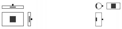 Figure C.4 from GB 38031-2025 (PDF p. 38). Sensor placement when the heating plate is built into the cell.
Same rule as external heating: sensor on the side opposite the heating device.
For the internal heating plate, the plate sits inside the cell at the centre of the coil or stack surface. The sensor goes on the cell's exterior, on the face opposite the heater plate.
Figure C.4 shows two layouts:
- a) Hard case and pouch cell: plate inside at coil/stack centre; sensor on the outer face directly opposite.
- b) Cylindrical cell: same principle adapted for the cylindrical geometry.
See internal heating plate for the plate specification.
Why opposite-side placement matters
The TR-confirmation rule in C.5.3.7 needs dT/dt ≥ 1 °C/s for > 3 s at the monitoring point. If the sensor sits next to the heater, dT/dt will hit 1 °C/s long before the cell is actually in TR — the heater alone produces that ramp. Placing the sensor on the opposite face means the 1 °C/s ramp can only be reached when the cell itself is generating heat internally, which is the signature of TR.
For the needle method, the same logic does not apply — the needle is not adding much heat — so the sensor goes near the short-circuit point to catch the first response.
Engineering note (non-normative): "Opposite side" is unambiguous for prismatic cells (large face vs. opposite large face) but underspecified for cylindrical cells, where the geometry suggests several reasonable interpretations. The OEM should record the exact sensor location in the C.3.5 d) 2 documentation and justify it against the figures.
Engineering note (non-normative): The < 1 s sampling rate combined with the > 3 s window in C.5.3.7 c) means at least 3 samples must show dT/dt ≥ 1 °C/s. With 100 ms sampling that's 30 samples — plenty of resolution. Do not run at exactly 1 s sampling because a single dropped sample can break the > 3 s confirmation.
Cross-references
- Trigger methods overview
- Needle penetration
- External heating
- Internal heating plate
- Runaway confirmation rule
Source: GB 38031-2025, Appendix C section C.5.3.6 and Figures C.2–C.4 (PDF p. 35–38).