Insulation resistance procedure
Insulation resistance is measured before all tests and after most tests on packs/systems (6.1.5). The post-test threshold is the universal pass criterion: ≥ 100 Ω/V (DC) or ≥ 500 Ω/V if an AC circuit is present, applied to clauses 5.2.1–5.2.16. Measurement uses one of two methods in Appendix B.
When and where to measure (6.1.5)
The battery pack or system should undergo insulation resistance testing before all tests and after certain tests. The test position is between the positive and negative output terminals and the electric platform. Specific test methods are provided in Appendix B.
The "electric platform" is the conductive outer shell, connected to the vehicle's electric platform.
Source: clause 6.1.5.
Test conditions (Appendix B.1)
The battery pack or system should be in a fully charged state as specified by the manufacturer. The test environment temperature should be 22°C ± 5°C, and the relative humidity should be 10% ~ 90%.
The internal resistance of the voltage detection tool should be no less than 10 MΩ. If the insulation monitoring function affects the insulation resistance test of the battery pack or system during measurement, the insulation monitoring function should be turned off, or the insulation resistance monitoring unit should be disconnected from the B-level voltage circuit to avoid affecting the measurement value. Otherwise, the manufacturer may choose whether to turn off the insulation monitoring function or disconnect the insulation monitoring unit from the B-level voltage circuit.
| Condition | Value |
|---|---|
| State | Fully charged per manufacturer |
| Temperature | 22 °C ± 5 °C |
| Relative humidity | 10 % – 90 % |
| Voltmeter internal R | ≥ 10 MΩ |
Source: clause B.1.
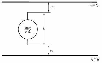 Figure B.1 from GB 38031-2025 (PDF p. 32). 测试对象 = test object; 电平台 = electric platform. Method 1 step 1: measure U₁ and U₁' between each output terminal and the electric platform.
Method 1 — voltage divider (B.2.1)
Two voltmeters measure the open-circuit imbalance, then a known resistor R₀ is added in parallel to the higher-voltage side. Insulation resistance Rᵢ is solved from the four voltage readings.
Procedure:
- Activate internal switches so the battery system is in the connected state.
- Use two identical voltmeters to simultaneously read the voltage between each output terminal and the electric platform. Higher reading = U₁, lower = U₁'.
- Add a known resistor R₀ (recommended 1 MΩ) in parallel between the U₁-side terminal and the electric platform.
- Read U₂ and U₂' simultaneously with the same two voltmeters.
- Compute Rᵢ from R₀, U₁, U₁', U₂, U₂', and the voltmeter internal resistance r using formula B.1 or B.2.
The PDF prints formulas B.1 and B.2 only as figures; the values to substitute are listed above. Pull the formulas from the PDF figures on page 33 when implementing.
Source: clause B.2.1.
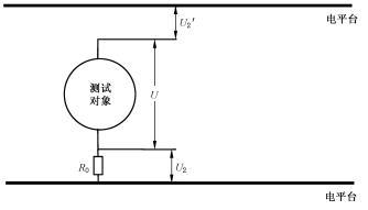 Figure B.2 from GB 38031-2025 (PDF p. 33). Method 1 step 2: add a known resistance R₀ (recommended 1 MΩ) in parallel between the U₁ side terminal and the electric platform; re-measure as U₂ and U₂'. Insulation resistance R_i is then computed via formula B.1 or B.2.
Method 2 — insulation resistance meter (B.2.2)
A direct measurement with a megohmmeter at elevated DC voltage.
Use an insulation resistance meter to separately measure the insulation resistance between the positive and negative output terminals of the battery pack or system and the electric platform.
| Parameter | Value |
|---|---|
| Measurement voltage | 1.5 × nominal voltage of pack/system, or 500 V DC, whichever is higher |
| Hold time | ≥ 30 s (until reading stabilises) |
Source: clause B.2.2.
Engineering note (non-normative): Method 2 is faster and standard for production lines. Method 1 is preferred when applying an external 500 V supply could damage onboard insulation monitors that the team would rather leave wired in. The standard does not prefer one method over the other — choose based on the test rig.
Pass thresholds (5.2.x)
The post-test value must meet:
| Circuit type | Minimum insulation resistance |
|---|---|
| DC only | ≥ 100 Ω/V |
| AC circuit present | ≥ 500 Ω/V |
The damp-heat cycling test (5.2.5) tightens timing — the measurement must be made within 30 minutes after the test ends. Compression (5.2.4) drops the leakage and housing-crack requirements but keeps the insulation threshold.
See pass/fail for the full pass-criterion model.
Source
Clauses 6.1.5, Appendix B (PDF pages 13, 32–33).