Compression (cell)
Verifies a fully charged cell crushed slowly between a flat surface and a 75 mm semi-cylindrical plate does not catch fire or explode.
| Clause (method) | 8.1.7 |
| Clause (pass criteria) | 5.1.6 |
| Object | cell |
| Status vs. 2020 | revised (method only) |
| Observation period | 1 h at test environment temperature |
Pass criteria
A battery cell, after undergoing the extrusion test according to 8.1.7, should not catch fire or explode.
There is no insulation requirement and no leakage/housing-crack requirement at cell level. (PDF p. 11)
Source: GB 38031-2025, clause 5.1.6 (PDF p. 11).
Pre-conditions
- Sample: A battery cell. (8.1.7.1)
- Active protection: Any additional active protection circuits or devices on the cell are removed. (8.1.1)
- Starting state: Cell standard-charged per clause 7.1.1. (8.1.7.2)
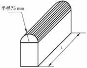 Figure 6 from GB 38031-2025 (PDF p. 21). Semi-cylindrical plate, radius 75 mm (半径75 mm), length L greater than the cell's compressed dimension.
Test parameters
| Parameter | Value | Source |
|---|---|---|
| Compression direction | Perpendicular to the cell's electrode plate, or the direction most likely to experience compression in the vehicle layout | 8.1.7.3 a) |
| Plate form | Semi-cylindrical | 8.1.7.3 b) |
| Plate radius | 75 mm | 8.1.7.3 b) |
| Plate length | L > cell dimension in the compressed direction (per Figure 6) | 8.1.7.3 b) |
| Compression speed | ≤ 2 mm/s | 8.1.7.3 c) |
| Stop condition (any one of, whichever first) | Voltage = 0, OR 15 % deformation, OR 100 kN, OR 1000 × test object mass | 8.1.7.3 d) |
| Hold at stop position | 10 min | 8.1.7.3 e) |
| Observation period | 1 h at test environment temperature | 8.1.7.4 |
Procedure
- Confirm the test object is a single battery cell with active protection devices removed. (8.1.1, 8.1.7.1)
- Standard-charge the cell using the method described in clause 7.1.1. (8.1.7.2)
- Position the cell in the fixture so the compression load applies perpendicular to the electrode plate, or in the in-vehicle direction most likely to be compressed. (8.1.7.3 a)
- Configure the compression plate: semi-cylindrical, r = 75 mm, with length greater than the cell's compressed dimension. (8.1.7.3 b)
- Begin compression at ≤ 2 mm/s. (8.1.7.3 c)
- Stop compression at the first of the following: cell voltage reaches 0 V, deformation reaches 15 % of the original cell dimension in the compression direction, compressive force reaches 100 kN, or compressive force reaches 1000 × the cell's mass. (8.1.7.3 d)
- Hold the plate at the stop position for 10 min. (8.1.7.3 e)
- Release the load and observe the cell for 1 h at the test environment temperature (22 °C ± 5 °C, per 6.1.1). (8.1.7.4)
- Record any fire or explosion event during compression, hold, or observation.
After-test observation
Observe the test object for 1 h at the test environment temperature. (8.1.7.4)
What changed from GB 38031-2020
- The test method was revised vs. the 2020 edition (8.1.7). The pass criterion (5.1.6) was not listed in the preface change list, so the requirement itself is unchanged.
- (Source: GB 38031-2025 preface, PDF p. 6.)
Migration impact: Cells previously certified under the 2020 method should be re-tested under the 2025 method ahead of the 2026-07-01 effective date for new type approvals.
Engineering notes (non-normative)
Engineering note (non-normative): The four stop conditions are OR'd, so the test ends at whichever fires first — but for a small cell the 1000 × mass force ceiling can stop compression well before any of the others. For a 50 g pouch cell that's only ~490 N, far below the 100 kN limit. Pre-compute which stop condition will dominate for your sample so you instrument the right channel.
Engineering note (non-normative): Voltage cannot be measured during compression once the tabs separate or short. Use a four-wire connection clamped well outside the compression footprint, and treat sudden V = 0 as either the genuine stop condition or instrumentation loss — record displacement and force continuously so you can disambiguate post-test.
Engineering note (non-normative): "Length L greater than the cell width" (Figure 6) is the minimum; in practice a 10–20 mm overhang on each side avoids edge-loading artefacts that cause the cell to roll out of the plate.
Related
- Glossary: Compression / extrusion
- Related tests: Pack/system compression (8.2.4)
- Source: GB 38031-2025, clause 8.1.7 (PDF p. 16); pass criteria in clause 5.1.6 (PDF p. 11).