Bottom impact
Verifies a vehicle-mounted battery pack survives underbody impact from road debris or obstacles without losing electrical safety. New in GB 38031-2025.
| Clause (method) | 8.2.16 |
| Clause (pass criteria) | 5.2.16 |
| Object | pack / system / entire vehicle |
| Status vs. 2020 | 🆕 new |
| Observation period | 2 h at test environment temperature |
Pass criteria
After the bottom impact test, the battery pack, system, or entire vehicle shall show no leakage, no housing crack, no fire, and no explosion. Insulation resistance after testing shall not be less than 100 Ω/V (DC), or 500 Ω/V if an AC circuit is present.
Source: GB 38031-2025, clause 5.2.16 (PDF p. 12).
Pre-conditions
- Sample: A battery pack or system mounted on the vehicle's bottom, or the corresponding entire vehicle. (8.2.16.1)
- Pre-treatment: Standard, per clause 7.2.
- SOC: Highest working SOC per clause 6.1.10.
- Insulation baseline: Measure before the test per Appendix B (clause 6.1.5).
Exemption
Battery packs or systems mounted on N-class vehicles with a minimum ground clearance of ≥ 200 mm under fully loaded conditions are not subjected to the bottom impact test. (8.2.16.1)
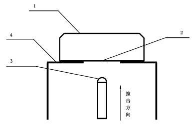 Figure 13 from GB 38031-2025 (PDF p. 28). 1 — test object · 2 — bottom of test object · 3 — impact head · 4 — test stand. Arrow indicates impact direction (撞击方向, "ji ji fang xiang", +z-axis).
Test parameters
| Parameter | Value | Source |
|---|---|---|
| Impactor shape | Hemispherical | 8.2.16.2 a) |
| Impactor diameter | Ø 30 mm | 8.2.16.2 a) |
| Impactor mass | 10 kg | 8.2.16.2 a) |
| Impactor material | 45# steel | 8.2.16.2 a) |
| Impact direction | +z-axis (upward into pack underside) | 8.2.16.2 b) |
| Number of impact positions | 3 | 8.2.16.2 c) |
| Position selection | Manufacturer-provided risk points covering front, middle, and rear of pack bottom | 8.2.16.2 c) |
| Impact energy (each) | 150 J ± 3 J | 8.2.16.2 d) |
| Required documentation | Technical documentation justifying selected risk points | 8.2.16.2 c) |
Procedure
- Confirm the test object is in scope (not exempt under 8.2.16.1).
- Fix the test object on the test platform per Figure 13. (8.2.16.2)
- Verify pre-conditions: SOC, pre-treatment complete, insulation baseline measured.
- Receive the manufacturer's three impact positions (front / middle / rear of pack bottom) and supporting documentation. (8.2.16.2 c)
- Configure the impactor: hemispherical, Ø 30 mm, 10 kg, 45# steel. (8.2.16.2 a)
- Perform impact 1 at the front position, +z direction, 150 J ± 3 J. (8.2.16.2 b, d)
- Perform impact 2 at the middle position, identical conditions.
- Perform impact 3 at the rear position, identical conditions.
- After all three impacts, observe at test environment temperature (22 °C ± 5 °C) for 2 hours. (8.2.16.3)
- After observation: re-measure insulation resistance per Appendix B. Inspect for leakage, housing cracks. Confirm no fire/explosion occurred during or after impact.
After-test observation
Observe the test object for 2 hours at the test environment temperature (22 °C ± 5 °C) after the third impact completes. (8.2.16.3)
During the observation period, the test object should be monitored for delayed effects (off-gassing, thermal events, leakage development).
What changed from GB 38031-2020
This test did not exist in GB 38031-2020. Added in the 2025 revision as a response to real-world incidents of underbody damage from road debris causing thermal events in EV battery packs.
Migration impact: Already-type-approved vehicle models must comply from 2027-08-01 (13 months after the standard takes effect). New type approvals from 2026-07-01. See Re-certification timeline.
Engineering notes (non-normative)
The notes below are practical interpretation, not part of the standard.
Engineering note (non-normative): The "three risk points" are at the manufacturer's discretion but must be technically justified in the submitted documentation. In practice, defensible selections target: (1) the thinnest section of the pack baseplate, (2) a cooling-plate weld seam or BMS junction footprint, and (3) a structural tie-down or rear cross-member. Selecting only "easy" positions is likely to be challenged during type approval.
Engineering note (non-normative): 150 J ± 3 J corresponds to roughly a 10 kg mass dropped from ~1.5 m, or a smaller object at higher velocity. The hemispherical Ø 30 mm impactor concentrates that energy on a small contact patch — so localized denting is expected; what fails is sealing/electrical, not gross structural integrity.
Engineering note (non-normative): The exemption for N-class vehicles with ≥ 200 mm ground clearance is geometric — those packs are unlikely to encounter underbody strikes in normal operation. Confirm the ground clearance measurement is taken at the lowest point of the pack, fully loaded (not unladen). Loaded clearance is what matters; some N-class trucks lose 50+ mm under full load.
Related
- Pass/fail criteria: What "no fire, no explosion" means, Insulation resistance thresholds
- Glossary: Housing crack, Leakage
- Reference: Vehicle category cheat sheet (for N-class definition and the ground-clearance exemption)
- Related tests:
- Vibration (8.2.1) — typically performed before bottom impact in a campaign sequence
- Compression (8.2.4) — also a mechanical pack test, different load case (lateral vs. underbody)
- Source: GB 38031-2025, clause 8.2.16 (PDF p. 27–28); pass criteria in clause 5.2.16 (PDF p. 12).