External heating
What is this: the surface-heater trigger method for thermal runaway, per Appendix C clause C.5.3.4. A planar, rod, block, or film heater is applied to the trigger cell's exterior to drive its temperature up until the cell runs away.
Specification
"C.5.3.4 External Heating Method to Trigger Thermal Runaway: Use a planar or rod-shaped heating device, with its surface covered by ceramic, metal, or insulating layers. For a block-type heating device with the same dimensions as the battery cell, it can be used to replace one of the battery cells, with direct contact with the surface of the triggering object; for a film heating device, it should always be attached to the surface of the triggering object. The heating area of the heating device should not exceed the surface area of the battery cell being heated. The heating surface of the heating device should be in direct contact with the surface of the battery cell, and the position of the heating device should correspond to the position of the temperature sensor specified in C.5.3.6. When heating the triggering object, the recommended heating power is shown in Table C.2. The triggering should stop when thermal runaway occurs or when the temperature at the monitoring point defined in C.5.3.6 reaches 300 °C."
Heating power — Table C.2
| Trigger object energy E (Wh) | Heating power (W) |
|---|---|
| E < 100 | 30 – 300 |
| 100 ≤ E < 400 | 300 – 1 000 |
| 400 ≤ E < 800 | 300 – 2 000 |
| E ≥ 800 | > 600 |
The bands are wide because the right power depends on the cell's thermal mass, surface area, and how aggressively the OEM wants to drive the test. Power high enough to reach the cell's TR onset before the heater itself fails is the operating constraint.
Heater types
The standard names four configurations:
| Configuration | When to use |
|---|---|
| Planar heater with ceramic/metal/insulating cover | The standard case for prismatic and pouch cells with a flat face exposed |
| Rod heater with ceramic/metal/insulating cover | Cylindrical cells, where the heater can run along the cell axis |
| Block heater sized to match the cell, replacing the cell | Hardest-driving option: the heater takes the geometric place of one cell and contacts the trigger cell directly across what would have been an inter-cell boundary |
| Film heater attached to the cell surface | When the cell cannot be removed from the pack and the only access is the cell exterior |
The block-replacement variant is significant because it keeps the geometry of the pack identical — the heater is exactly the size of a cell, sitting in a cell slot. That preserves the propagation path the test is meant to verify.
Constraints
- Heating area ≤ cell surface area. (C.5.3.4)
- Heating surface in direct contact with the cell surface. (C.5.3.4)
- Heater position corresponds to the temperature sensor position in C.5.3.6 — i.e. the sensor sits on the cell face directly opposite the heater. (C.5.3.4)
Stop conditions
"...stop when thermal runaway occurs or when the temperature at the monitoring point defined in C.5.3.6 reaches 300 °C."
Two ways to stop the heater:
- TR confirmed under the (a OR b) AND c rule. This is the success case.
- Monitor T = 300 °C without TR. This is the no-trigger case — the cell got hot but did not run away. The OEM then has to demonstrate that none of the three recommended methods would have triggered TR (see runaway confirmation).
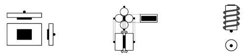 Figure C.3 from GB 38031-2025 (PDF p. 38). a) hard case and pouch cell; b) cylindrical cell — variant I; c) cylindrical cell — variant II. Sensor sits opposite the heating device on each cell variant.
Sensor placement
"During heating triggering, the temperature sensor should be placed on the side opposite to the heat conduction, that is, installed on the side opposite the heating device (as shown in Figure C.3, Figure C.4)." (C.5.3.6 c)
The sensor must be on the opposite face of the cell from the heater. This is what makes the dT/dt ≥ 1 °C/s for > 3 s rule meaningful — direct conduction from the heater would otherwise dominate the thermal signal. See monitoring and sensors for the full placement rationale and Figure C.3 layouts.
Tradeoffs
Pros: - Cell unmodified — the trigger cell can be a stock production cell. - Repeatable: heating power and contact area are well-defined. - No pack housing penetration needed if the heater can be installed at pack assembly.
Cons: - Slow: minutes from heater on to TR, depending on power and cell size. - The 300 °C cutoff means a thermally robust cell may simply not trigger. - Heater materials can off-gas during the test, contaminating the smoke observation window (see smoke and the passenger compartment).
Engineering note (non-normative): Choose the upper end of the Table C.2 power band when the cell is thermally well-coupled to the cooling system or to neighbouring cells, because heat will be drained away before TR onset. Use the lower end for cells that are well-isolated thermally — too much power can produce surface decomposition before the bulk cell reaches TR onset, leading to a misleading 300 °C cutoff.
Engineering note (non-normative): The "heater position corresponds to sensor position" requirement (C.5.3.4) is asymmetric: the sensor goes on the opposite face. So "corresponds" means "matches the geometry such that the sensor face is opposite the heater face," not "co-located with the heater." Read C.5.3.4 and C.5.3.6 c) together.
Cross-references
- Trigger methods overview
- Needle penetration
- Internal heating plate
- Monitoring and sensors
- Runaway confirmation rule
Source: GB 38031-2025, Appendix C section C.5.3.4 and Table C.2 (PDF p. 36); sensor placement in C.5.3.6 c) and Figure C.3 (PDF p. 37–38).